Skip to content

Product guide

Patriot Plus flag hinge — fitting, adjustment and removal

Identify the Trojan Patriot Plus 0785-series flag hinge, check its step height and follow the supplied fitting, 3D adjustment, removal and care instructions.

WhatsApp us All guides

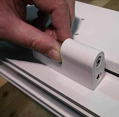
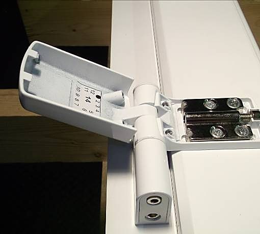
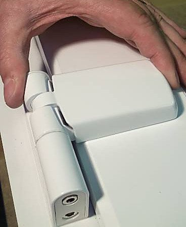
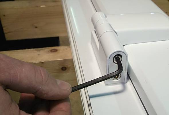
White Patriot Plus flag hinge fitted to a profile, with a hex key at the compression adjustment.

Identify your hardware

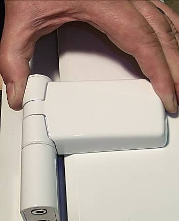
The Patriot Plus is a lift-off, 3D adjustable flag hinge for uPVC and composite doors. The supplied guide describes it as pre-assembled and non-handed, for left- or right-hung doors, with an anti-lift feature and concealed fixings.

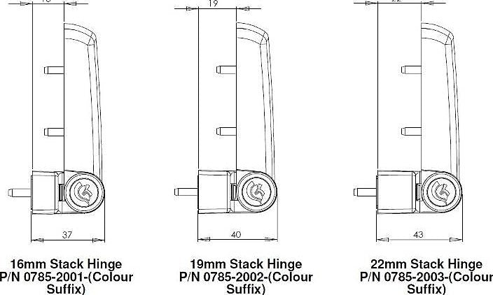
Identify the Trojan 0785 series and the correct step height: 16 mm — 0785-2001; 19 mm — 0785-2002; 22 mm — 0785-2003. The colour suffix is added to the base part number. The original reference drawings are included below.

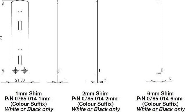
Do not confuse a complete hinge with a separately sold 1 mm, 2 mm or 6 mm hinge packer. The packer-fitting step applies where a packer is required; the complete fitting, adjustment and removal procedures apply to the hinge assembly.

This guide applies to

Trojan Patriot Plus 0785-series complete flag hinges in the 16 mm, 19 mm and 22 mm step heights described in the supplied Rev. 1 guide. Standalone hinge packers are accessories, not complete hinges.

Based on the UPVCSTORE fitting and installation guide marked Rev. 1. The PDF does not identify a separate physical hardware revision; exact stocked-variant applicability remains to be confirmed.

Check compatibility

The supplied guide covers Patriot Plus flag hinges for uPVC and composite doors, in 16 mm, 19 mm and 22 mm up-stand/step heights. It describes one non-handed hinge for left- or right-hung doors and a symmetrical drilling jig.

The source specifies up to 80 kg sash weight using three hinges. Fixing screws must suit the reinforcing used. Inner sash-plate screws must engage the reinforcing; shorter outer screws avoid breaking through the other side.

The guide does not establish compatibility with every door profile or every similarly named hinge. The related store product includes both hinges and standalone packer accessories; a packer selection alone does not identify a complete hinge.

Measurements

Step heights: 16 mm, 19 mm or 22 mm. Packers/shims: 1 mm, 2 mm or 6 mm, in white or black. Drilling jig: Jig-0036.

Location-pin drilling: Ø4.0 mm, through the profile skin only. Recommended screws: Ø4.8 mm. Exact screw lengths depend on the reinforcing and fixing position; the source does not give universal lengths.

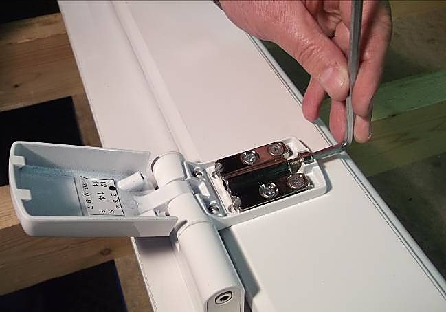
Compression adjustment: ±1.5 mm with a 4 mm hex key. Height adjustment: +8 mm / −0 with a 5 mm hex key. Lateral adjustment: ±6 mm with a 5 mm hex key.

The original drawings below retain the source’s dimension labels. Some edge labels are cropped in the supplied artwork; no missing numbers have been reconstructed.

Part numbers and dimension drawings

3 steps
When this task applies

Trojan Patriot Plus 0785-series complete flag hinges in the 16 mm, 19 mm and 22 mm step heights described in the supplied Rev. 1 guide. Standalone hinge packers are accessories, not complete hinges.

Before you start

Original reference drawings from the supplied Patriot Plus guide. These show the hinge step heights, plan/projection and packers.

  1. 16 / 19 / 22 mm stack heights

    The guide lists three Patriot Plus hinge step heights: 16 mm (0785-2001), 19 mm (0785-2002) and 22 mm (0785-2003). Add the colour suffix to the base part number when ordering.

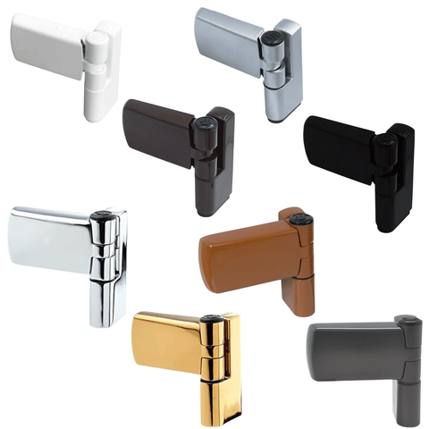
    The original stack-height drawing is reproduced below. The source lists finishes as White, Black, Brown, Oak, Anthracite Grey, Chrome, PVD Gold and Satin Silver.

    16 / 19 / 22 mm stack heights
  2. Hinge plan & flag projection

    Before this step
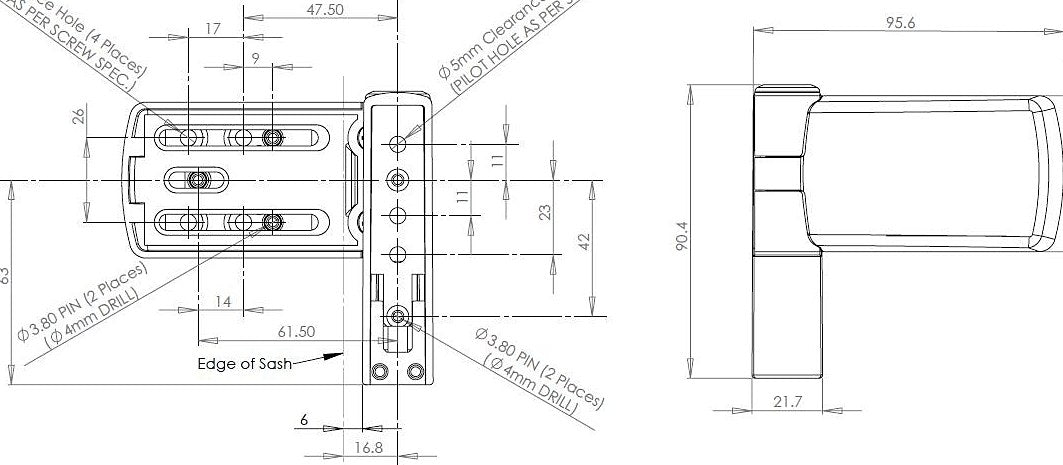
    Some labels at the edges of this supplied drawing are cropped. Missing dimensions must be clarified before they are used.

    The original drawing shows the hinge plan, flag projection and fixing/pin positions. The fitting procedure in this guide uses the Jig-0036 drilling jig and a Ø4.0 mm drill for the location-pin holes.

    Hinge plan & flag projection
  3. 1 / 2 / 6 mm packers

    The guide lists 1 mm, 2 mm and 6 mm packers/shims, available in white or black. Its order table gives part numbers 0785-014-1, 0785-014-2 and 0785-014-6 respectively.

    The original packer drawing is reproduced below. A packer is an accessory used where required; it is not a complete hinge.

    1 / 2 / 6 mm packers

Fit the Patriot Plus flag hinge

20 steps
When this task applies

Trojan Patriot Plus 0785-series complete flag hinges in the 16 mm, 19 mm and 22 mm step heights described in the supplied Rev. 1 guide. Standalone hinge packers are accessories, not complete hinges.

What you need

  • Jig-0036 drilling jig
  • 5 mm hex key for jig set-up
  • Ø4.0 mm drill bit for location-pin holes
  • Cross-head screwdriver
  • Flat screwdriver
  • Ø4.8 mm screws, with lengths suited to the reinforcing and fixing position
  • A suitable packer, where required
Before you start

The hinge is supplied pre-assembled and non-handed. Fitting has three stages: prepare and drill, fit to the frame, then fit to the sash. The 3D adjustment task follows fitting.

Set the drilling jig to the door’s up-stand and hand. Jig-0036 is symmetrical and works for either hand. Use fixings suited to the reinforcing used.

  1. Set the jig step height

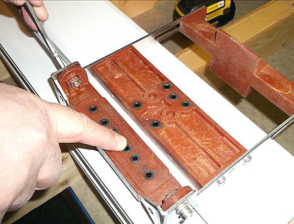
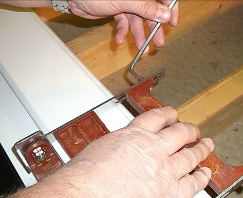
    Slide the frame block of the jig down until it sits on the frame, then lock it in position with a 5 mm hex key. This sets the jig to match the up-stand of the door.

    Set the jig step height
    Expected result

    The jig frame block sits on the frame and is locked to the door up-stand.

  2. Set the grip onto the sash

    Slide the clamp block until it sits against the inner edge of the sash, then tighten with the 5 mm hex key so the jig is held square and secure for drilling.

    Set the grip onto the sash
    Expected result

    The jig is held square and secure against the inner edge of the sash.

  3. Drill through the outer skin only

    Before this step
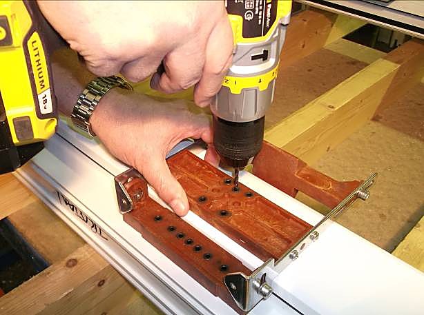
    Drill through the profile skin only. On the frame side, use only the left- or right-hand pin locations required for the door’s hand.

    Using a Ø4.0 mm drill bit, drill through the skin of the profile only at the pin locations marked on the jig. On the frame side, drill only the left- or right-hand pin locations as required for the door’s hand. If not using drill-point screws, pilot the remaining holes as needed.

    Drill through the outer skin only
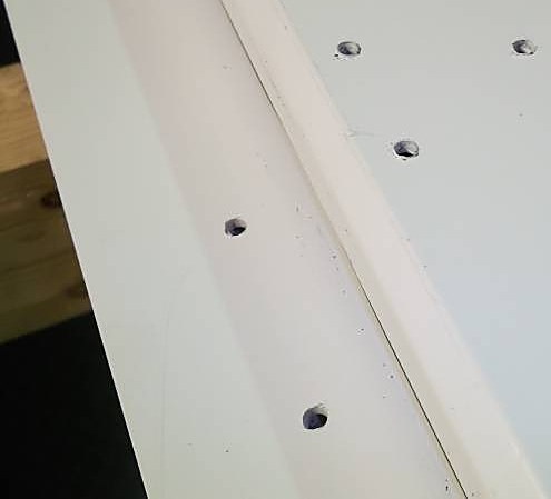
  4. Frame — pins drilled

    The source photograph shows the frame pin locations after drilling. The hinge is non-handed and the jig is symmetrical, so the same jig and hinge serve both hands; only the choice of frame pin row (LH or RH) changes. The recommended screw size is Ø4.8 mm.

    Frame — pins drilled
  5. Separate the frame mount (if required)
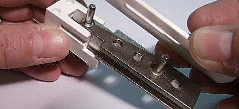
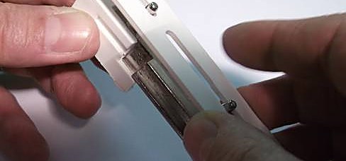
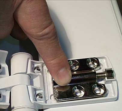
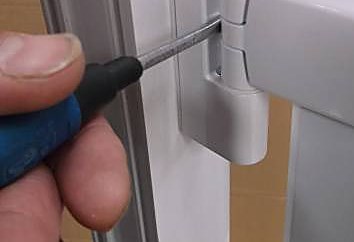
    The hinge is normally supplied latched together. If you need to separate the frame mount, insert a flat screwdriver behind the metal tang and lever it towards the pivot pin; keeping the screwdriver in place, slide the frame mount out.

    Separate the frame mount (if required)
  6. Fit a packer if required

    Where a packer is needed, locate its two pips into the corresponding holes on the frame-mount moulding so it sits flat and square against the frame.

    Fit a packer if required
    Expected result

    The packer sits flat and square, with both pips located in the corresponding holes.

  7. Push fully down

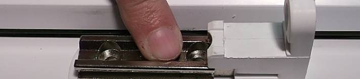
    Align the location pins with the holes in the frame, insert the pins and push the frame mount fully down.

    Push fully down
    Expected result

    The frame mount is pushed fully down with its location pins inserted.

  8. Fix in 3 places

    Before this step

    The fixing screws must be the correct length to engage the reinforcing.

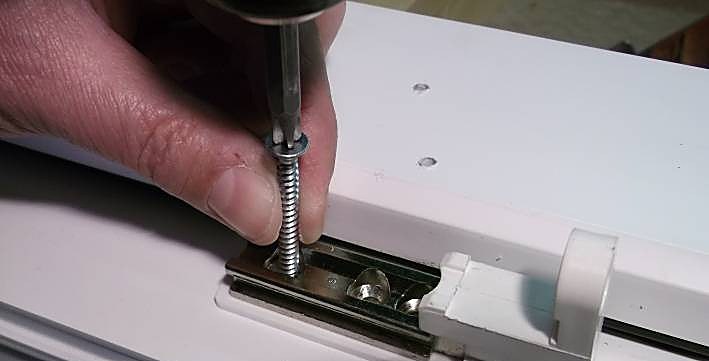
    Secure the frame mount with screws in three places, ensuring the screws are the correct length to engage with the reinforcing.

    Fix in 3 places
  9. Slide on

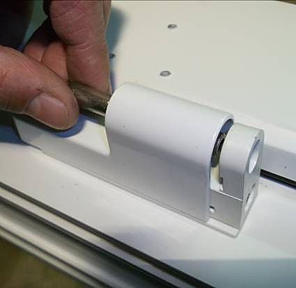
    Slide the frame body casting onto the frame mount.

    Slide on
  10. Push down until it clicks

    Push the frame body casting all the way down until it clicks into place and sits flush with the bottom of the frame-mount moulding.

    Push down until it clicks
    Expected result

    The casting has clicked into place and sits flush with the bottom of the frame-mount moulding.

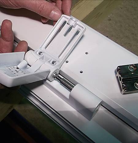
  11. Flag assembly + screw plate

    Slide the flag assembly onto the frame-mount pivot pin and push it all the way down.

    Flag assembly + screw plate
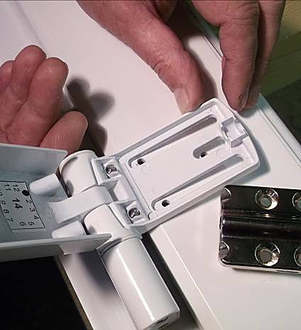
  12. Align to sash plate

    Align the location-pin holes with the sash plate.

    Align to sash plate
  13. Push fully down

    Insert the screw plate with its location pins into the pre-drilled holes and push fully down.

    Push fully down
    Expected result

    The screw plate location pins are inserted into the pre-drilled holes and the plate is pushed fully down.

  14. Inner holes — long screws

    Before this step
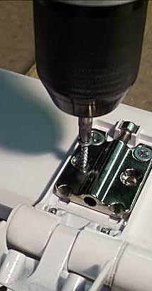
    Screw length matters: long screws inner, short screws outer. Using the wrong length can fail to grip the reinforcing or break out through the profile.

    Fix the screw plate with 2 × Ø4.8 mm screws in the inner holes. Use long screws here to engage the reinforcing.

    Inner holes — long screws
  15. Outer holes — short screws

    Before this step
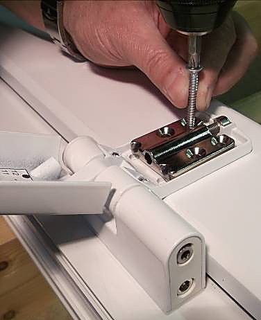
    Use shorter screws in the outer holes to avoid breaking through the other side. The source does not give universal screw lengths.

    Fit 2 × shorter screws in the outer holes to avoid breaking through the other side.

    Outer holes — short screws
  16. Rotate cover closed

    Rotate the flag cover towards the closed position.

    Rotate cover closed
  17. Push cover down

    With the flag cover flat on the profile, push it back towards the frame mount.

    Push cover down
  18. Click into place

    Continue pushing the flag cover back towards the frame mount until it clicks into place.

    Click into place
    Expected result

    The cover has clicked into place.

  19. Tighten retention screws

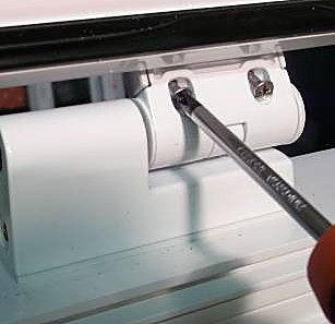
    Lift the sash to expose the flag-cover retention screws on the underside and fully tighten them clockwise with a cross-head screwdriver.

    Tighten retention screws
  20. Fit cover cap

    Replace the sash and fit the cover cap.

    Fit cover cap
    Expected result

    The sash is replaced and the cover cap fitted.
Completion checks

Check the source’s fitting endpoints: frame body casting flush with the bottom of the mount moulding; flag cover clicked into place; retention screws fully tightened; sash replaced and cover cap fitted. Continue with 3D adjustment.

Adjust compression, height and lateral position

3 steps
When this task applies

Trojan Patriot Plus 0785-series complete flag hinges in the 16 mm, 19 mm and 22 mm step heights described in the supplied Rev. 1 guide. Standalone hinge packers are accessories, not complete hinges.

What you need

  • 4 mm hex key for compression
  • 5 mm hex key for height and lateral adjustment
Before you start

All three adjustments are independent and made in situ with the door hung. Work in small increments and keep settings balanced across every hinge for a square, well-sealed door.

  1. Compression: ±1.5 mm

    Before this step

    Keep compression even across all hinges.

    Use a 4 mm hex key. Rotate it clockwise or anti-clockwise to set compression against the weatherseal. Positive “click” positions are felt — two in each direction from centre. Keep compression even across all hinges.

    Compression — 4 mm hex key
  2. Height: +8 mm / −0

    Before this step

    Make sure the door’s weight is evenly distributed across all hinges.

    Use a 5 mm hex key. Rotate it clockwise to raise the door to the required height, with no gap created between the flag and base. Make sure the door’s weight is evenly distributed across all hinges.

    Height — 5 mm hex key
    Expected result

    The door is raised to the required height without a gap between the flag and base.

  3. Lateral: ±6 mm

    Before this step

    Distribute the lateral adjustment evenly across all hinges.

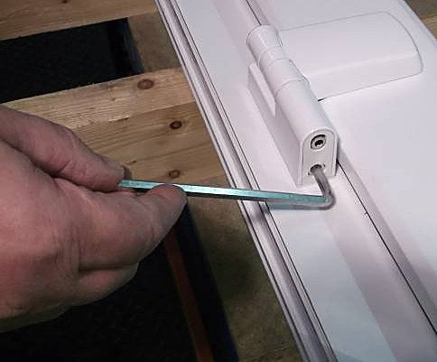
    Use a 5 mm hex key. Rotate it clockwise or anti-clockwise to move the door laterally and centre it within the frame. Distribute the adjustment evenly across all hinges.

    Lateral — 5 mm hex key
    Expected result

    The door is centred within the frame with the adjustment distributed across the hinges.
Completion checks

Spread weight, compression and lateral movement evenly across all hinges rather than loading a single hinge. Keep the door centred and aligned; height adjustment should not create a gap between the flag and base.

Remove and refit the door

5 steps
When this task applies

Trojan Patriot Plus 0785-series complete flag hinges in the 16 mm, 19 mm and 22 mm step heights described in the supplied Rev. 1 guide. Standalone hinge packers are accessories, not complete hinges.

What you need

  • Cross-head screwdriver for cover retaining screws
  • Screwdriver to gently assist behind the knuckle if the cover does not release by hand
Before you start

The anti-lift feature means the door cannot simply be lifted off — the flag covers must be released first. Work one hinge at a time.

  1. Undo the cover screws

    Open the door to reach the cover retaining screws. These are self-retaining: unscrew them fully to release the cover — they will not fall out.

    Undo the cover screws
  2. Pull towards centre

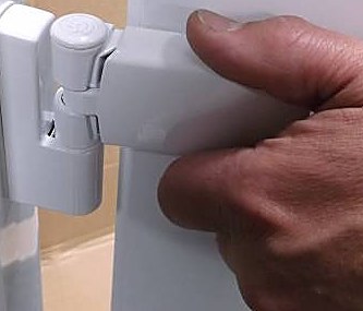
    Pull the cover out towards the centre of the door; a click is heard as it releases.

    Pull towards centre
    Expected result

    The cover clicks as it releases.

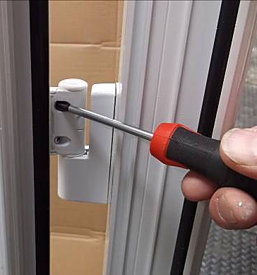
  3. Assist behind the knuckle

    Before this step
    Work one hinge at a time. Release every flag cover before lifting the door off.

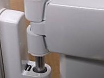
    If the cover does not come away by hand, use a screwdriver behind the knuckle to gently assist. Repeat the cover-release procedure on each hinge.

    Assist behind the knuckle
  4. Lift the door off

    Before this step

    The anti-lift feature means the door cannot simply be lifted off: all flag covers must be released first.

    With every cover released, lift the door clear of the frame pivots.

    Lift the door off
  5. Refit the door

    To refit, reverse the process: lower the door onto the pivots, push each flag cover back until it clicks, and re-tighten the screws.

    Expected result

    Each flag cover is clicked back into place and the screws are re-tightened.
Completion checks

Before lifting the door off, every flag cover must be released. When refitting, lower onto the pivots, click each cover back into place and re-tighten its screws.

Care and maintenance

2 steps
When this task applies

Trojan Patriot Plus 0785-series complete flag hinges in the 16 mm, 19 mm and 22 mm step heights described in the supplied Rev. 1 guide. Standalone hinge packers are accessories, not complete hinges.

What you need

  • Soft cloth
  • Mild detergent
Before you start

The supplied guide calls for mild cleaning and periodic checks of fixings and adjustment.

  1. Clean the hinge

    Before this step

    Never use abrasive or solvent-based cleaners.

    Clean with a soft cloth and mild detergent only.

  2. Check fixings and adjustments

    Periodically check that fixings remain tight and adjustments are even across all hinges.

    Expected result

    Fixings remain tight and adjustments are even across all hinges.

Completion checks

Keep fixings tight and adjustments even across the hinges. The supplied guide states a 10-year mechanical guarantee when correctly installed and maintained; current warranty terms have not been independently checked as part of this conversion.

Troubleshooting

Frame mount needs separating: the fitting task describes releasing the metal tang with a flat screwdriver while sliding out the frame mount.

Flag cover does not release by hand: the removal task describes gently assisting behind the knuckle with a screwdriver, then repeating the release on each hinge.

Door will not lift off: the guide identifies an anti-lift feature. Every flag cover must be released before the door is lifted clear of the pivots. The PDF supplies no separate fault-diagnosis chart beyond these points.

Buy this part

The replacement hardware covered by this guide. Check the identification and measurements above before ordering.
Need a hand identifying your part?

If the model, step height, door profile or fixing requirements do not match this guide, ask for product identification help before proceeding.